DoF on Edges in Three Dimensions
We describe general idea of the data structures generated in subroutine
dofedge for two dimensional triangular grids. We refer to Simplicial Complex in Two Dimensions for the discussion of ordering and orientation of edges.
[elem2edge,edge,elem2edgeSign,edgeSign] = dofedge(elem) constructs data structure for finite elements associated to edges including CR nonconforming element, Ravairt-Thomas element, and Nedelec element etc.
In the output
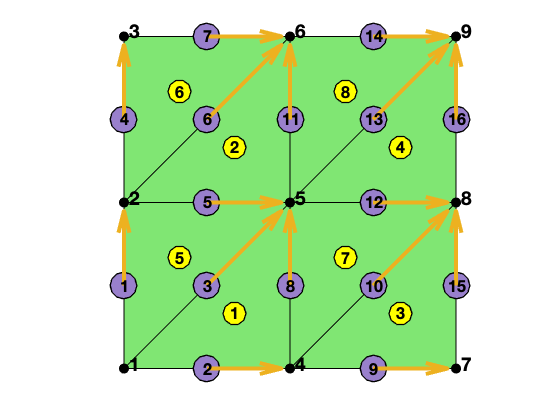
-elem2edge: the elementwise pointer from elem to edge. In each triangle, the opposite indexing is used for its three edges, e.g., elem2edge(t,1) is the global index of the first edge consisting of vertices [2 3] of triangle t.
-edge: the edge matrix is sorted s.t. edge(:,1)<edge(:,2). The orientation of edge is induced by the ascend ordering of vertices.
-elem2edgeSign: records the consistency of the local edge locEdge = [2 3; 3 1; 1 2] and the global edge orientation.
elem2edgeSign = -1 if the local edge orientation is inconsistent with the global one, i.e. elem(:,locEdge(:,1)) > elem(:,locEdge(:,2)).
When both elem and local edges are ascend ordered (i.e. locEdge = [2 3; 1 3; 1 2] and elem(:,1)<elem(:,2)<elem(:,3) ), elem2edgeSign = [1 1 1]. In this case, no need to use elem2edgeSign.
When elem is the ascend ordering and locEdge = [2 3; 3 1; 1 2] is the induced ordering, then elem2edgeSign = [1 -1 1], i.e., only the 2nd edge [3 1] is inconsistent. In this case, the pattern is also known and no need to call dofedge.
-edgeSign: As the lcoal edge is the induced ordering, one interior edge will be shared by two triangles with opposite orientation. edgeSign = 1 if the edge is consistent with the local edge of its first element, equals -1 otherwise.
See also dof3edge, dof3face
Example
% Generate edge and elem2dof
[node,elem] = squaremesh([0,1,0,1],1/2);
T = auxstructure(elem);
elem2edge = T.elem2edge;
edge = T.edge;
edge2elem = T.edge2elem;

showmesh(node,elem);
findnode(node,'all');
findelem(node,elem,'all');
findedge(node,edge,'all','vec');

display(elem);
display(elem2edge);
display(edge);
elem =

     4     5     1
     5     6     2
     7     8     4
     8     9     5
     2     1     5
     3     2     6
     5     4     8
     6     5     9
elem2edge =
8�3 uint32 matrix
    3    2    8
    6    5   11
   10    9   15
   13   12   16
    3    5    1
    6    7    4
   10   12    8
   13   14   11
edge =
16�2 uint32 matrix
   1   2
   1   4
   1   5
   2   3
   2   5
   2   6
   3   6
   4   5
   4   7
   4   8
   5   6
   5   8
   5   9
   6   9
   7   8
   8   9
NT = size(elem,1); NE = size(edge,1);
elem2edgeSign = ones(NT,3);
totalEdge = uint32([elem(:,[2,3]); elem(:,[3,1]); elem(:,[1,2])]);
idx = (totalEdge(:,1)>totalEdge(:,2));
elem2edgeSign(idx) = -1;

display(elem2edgeSign);
elem2edgeSign =

    -1     1     1
    -1     1     1
    -1     1     1
    -1     1     1
     1    -1    -1
     1    -1    -1
     1    -1    -1
     1    -1    -1
Comments