Simplicial Complex in Three Dimensions
We describe the data structure of the simplicial complex associated to a three-dimensional triangulation give by node,elem. The node records the coordinates of vertices and elem is the pointer from local to global indices of vertices. See Basic mesh data structure.
A brief summary.
edge: ascending ordering, i.e.edge(:,1)<edge(:,2)face: ascending ordering, i.e.face(:,1)<face(:,2)<face(:,3)elem: the default one is the positive ordering and the ascending ordering is mainly used for edge and face elements.- Use
[elem,bdFlag] = sortelem3(elem,bdFlag)to change the ordering to the ascending ordering. Note thatbdFlagshould be switched together. - Use
[elem,idx,area,bdFlag] = fixorder3(node,elem,bdFlag)to change the ordering to the positive ordering.
The multigrid solvers use the original ordering of
elemobtained from either uniform refinement or bisection methods. So letelemold=elemand useelemoldin multigrid solvers.
- Examples on the usage:
Poisson3RT0; Maxwell; Maxwell2;
Outline
We describe the data structure of the simplicial complex associated to a
two-dimensional triangulation give by node,elem. The node records
the coordinates of vertices and elem is the pointer from the local to
the global indices of vertices. See Basic mesh data structure.
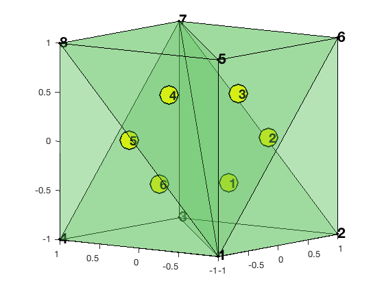
node = [-1,-1,-1; 1,-1,-1; 1,1,-1; -1,1,-1; -1,-1,1; 1,-1,1; 1,1,1; -1,1,1];
elem = [1,2,3,7; 1,6,2,7; 1,5,6,7; 1,8,5,7; 1,4,8,7; 1,3,4,7];
clf; showmesh3(node,elem,[],'FaceAlpha',0.25);
view([-53,8]);
axis on
findelem3(node,elem);
findnode3(node);
The integers N, NE, NF, NT represents the muber of vertice, edges, faces, tetrahedron
respectively.
The corresponding simplicial complex consists of vertices, edges, faces, and tetrahedron. We shall discuss the following three issues:
- Indexing of simplexes
- Ordering of vertices of simplexes
- Orientatoin of simplexes
The indexing and ordering are related and the ordering and orientation
are mixed together. However the indexing has nothing to do with the
orientation. The indexing and ordering are the combinarotry structure,
i.e. only elem is needed, while the orientation also depends on node,
the geometry emembdding of vertices.
For indexing, ordering and orientation, there are always two versions: local and global. The pointer from the local and the global version is the most complicated issue.
Indexing
The indexing refers to the numbering of simplexes, e.g., which face is
numbered as the first one. Each simplex in the simplicial complex has a unique index which is called the global index. Inside one tetrahedron, the four vertices and four
faces have their local index 1:4.
In the assembling procedure of finite element methods, an element-wise
matrix using the local index is firstly computed and then assembled to get a
big matrix using the global index. Thus the pointer from the local
index to the global one is indispensible. For bases independent of
the ordering and orientation, e.g., P1 and P2 elements, the pointer of indices
is sufficient.
Pointers of vertices
The NT x 4 matrix elem is indeed the pointer of the vertex indices. For example elem(t,1)=25 means the first vertex of t is the 25-th vertex.
Similiary, the NE x 2 matrix edge records the vertices pointer of edges.
Local indexing of edges and faces
The tetrahedron consists of four vertices indexed as [1 2 3 4]. Each
tetrahedron contains four faces and six edges.
-
Opposite indexing
locFace = [2 3 4; 1 3 4; 1 2 4; 1 2 3]; -
Lexicographic indexing
locEdge = [1 2; 1 3; 1 4; 2 3; 2 4; 3 4];
In locFace, the i-th face is opposite to the i-th vertices and thus called opposite indexing. In locEdge, it is the lexicographic indexing which is induced from the lexicographic ordering of the six edges. The ordering of vertices inside each face or edge will not
change the indexing. For example, the following locFacec and locEdged
has the same indexing as locFace and locEdge but with a different ordering
of vertices.
locFacec = [2 3 4; 1 4 3; 1 2 4; 1 3 2];
locEdge = [2 1; 3 1; 4 1; 3 2; 4 2; 4 3];
Indeed any permutation of vertex indices will represent the same simplex and will not change the indexing of the simplex. The ordering of vertices will affect the orientation and will be discussed later.
For a face consists of three vertices [1 2 3], there are two indexing
schemes of its three edges.
- Oppoiste indexing
[2 3; 3 1; 1 2] - Lexicographic indexing
[1 2; 1 3; 2 3]
Each indexing scheme has its advantage and disadvantage and which one to use depends on the consideration of ordering and orientation.
Global indexing of edges and faces
One can easily collect edges and faces elementwise. The issue is the
duplication. For example, each interior face will be counted twice. The
unique function is applied such that each edge or face has a unique
global index.
Edge and Face
totalEdge = uint32([elem(:,[1 2]); elem(:,[1 3]); elem(:,[1 4]); ...
                    elem(:,[2 3]); elem(:,[2 4]); elem(:,[3 4])]);
sortedTotalEdge = sort(totalEdge,2);
[edge, ~, je] = unique(sortedTotalEdge,'rows');
display(edge);

totalFace = uint32([elem(:,[2 3 4]); elem(:,[1 4 3]); ...
                    elem(:,[1 2 4]); elem(:,[1 3 2])]);
sortedTotalFace = sort(totalFace,2);
[face, i2, jf] = unique(sortedTotalFace,'rows');
display(face);
edge =

  19x2 uint32 matrix

   1   2
   1   3
   1   4
   1   5
   1   6
   1   7
   1   8
   2   3
   2   6
   2   7
   3   4
   3   7
   4   7
   4   8
   5   6
   5   7
   5   8
   6   7
   7   8
face =

    18x3 uint32 matrix

   1   2   3
   1   2   6
   1   2   7
   1   3   4
   1   3   7
   1   4   7
   1   4   8
   1   5   6
   1   5   7
   1   5   8
   1   6   7
   1   7   8
   2   3   7
   2   6   7
   3   4   7
   4   7   8
   5   6   7
   5   7   8
In iFEM, N,NE,NF,NT represents the number of vertices, edges, faces and tetrahedrons, respectively.
N = size(node,1); NT = size(elem,1); NF = size(face,1); NE = size(edge,1);
In the assembling procedure, the matrix is always computed elementwise and then assemble to a big one. A pointer from the local index to its global one is thus indispensable.
Elementwise pointers
elem2node = elemelem2face(1:NT, 1:4)elem2edge(1:NT, 1:6)
Such information is exactly stored in the output of unique function. For example, elem2face(t,1) = 17 means the first face of t (spanned by [2 3 4]) is the 17-th face in the face matrix.
N = size(node,1); NT = size(elem,1); NF = size(face,1); NE = size(edge,1);
elem2edge = uint32(reshape(je,NT,6));
elem2face = uint32(reshape(jf,NT,4));
display(elem2edge);
display(elem2face);
elem2edge =

  6x6 uint32 matrix

    1    2    6    8   10   12
    3    2    6   11   13   12
    4    5    6   15   16   18
    4    7    6   17   16   19
    1    5    6    9   10   18
    3    7    6   14   13   19
elem2face =

	6x4 uint32 matrix

   13    5    3    1
   15    5    6    4
   17   11    9    8
   18   12    9   10
   14   11    3    2
   16   12    6    7
Face to edge Pointer
face2edge(1:NF,1:3) records the global indices of three edges of a face. This pointer depends on the ordering of vertices of faces and the indexing of local edges. We list the following two important cases. Other combinations are possible but not attractive.
- Ascend ordering.
All local faces and local edges are ascending ordered.
locFace = [2 3 4; 1 3 4; 1 2 4; 1 2 3];
locEdge = [1 2; 1 3; 1 4; 2 3; 2 4; 3 4];
edgeOfFace = [1 2; 1 3; 2 3];
locFace2edge = [4 5 6; 2 3 6; 1 3 5; 1 2 4];
- Consistent ordering
The local face is ordered such that the corresponding orientation is consistent with the induced orientation from the tetrahedron.
locFace = [2 3 4; 1 4 3; 1 2 4; 1 3 2];
locEdge = [1 2; 1 3; 1 4; 2 3; 2 4; 3 4];
edgeOfFace = [2 3; 3 1; 1 2];
locFace2edge = [6 5 4; 6 2 3; 5 3 1; 4 1 2];
The global pointer can be obtained from the composition of elem2face and
locFace2edge. For example, for the ascending ordering scheme,
face2edge(elem2face(:,1),:) = elem2edge(:,[4 5 6]);
face2edge(elem2face(:,2),:) = elem2edge(:,[2 3 6]);
face2edge(elem2face(:,3),:) = elem2edge(:,[1 3 5]);
face2edge(elem2face(:,4),:) = elem2edge(:,[1 2 4]);
Ordering
We discuss the ordering of vertices of simplexes. The local and the global ordering may not be consistent and a sign array can be used to record the inconsistency.
The local ordering refers to the ordering of vertices in locFace or
locEdge, i.e. the ordering of the local index of vertices. For elements
associated to faces or edges, the local ordering could be used in the
formulation of the local basis and thus the ordering does matter.
The global ordering refers to the ordering of vertices in face or
edge, i.e., the ordering of the global index of vertices. Note that in either local or global ordering, permutation of vertices will represent the same simplex. To fix an ordering we need extra information.
elem
The local ordering is always [1 2 3 4]. Any permutation of four vertices of a tetrahedron still represents the same tetrahedron. Such freedom provides a room to record more information like: a global ordering of vertices, an orientation of element, and refinement rules (uniform refinement or bisection) etc.
For 2-D triangulations, three vertices of a triangle in 2-D is sorted counter-cloclwise and the first vertex is chosen as the newest vertex. Such ordering enables the efficient implementation of local refinement and coarsening in 2-D; see Bisection in Two Dimensions and Coarsening in Two Dimensions.
In 3-D, for the longest edge bisection, the newest vertex (with the maximal generation) is stored as the last (4-th) vertex of a tetrahedron. For 3-D Red Refinement.), the ordering determines the shape regularity of refined triangulation. Permutation of vertices in elem could deteriorate the angle condition after the refinement.
We shall preserve the ordering of elem from the mesh refinement and
coarsening since they are more subtle. We switch the ordering inside the subroutines when generating data structure for finite element basis and assembleing the
matrix equation.
Two types of ordering of elem is of particular importantance
- ascend ordering
- positive ordering
In the ascending ordering, the vertices of elem is sorted such that
elem(t,1) < elem(t,2) < elem(t,3) < elem(t,4)
Ascend ordering will benefit the construction of local bases for high
order Lagrange elements and in general bases with orientation dependent. This can be easily achieved by elem = sort(elem,2). But to include correct boundary conditions, one has to rotate the boundary flag accordingly using sortelem3.
bdFlag = setboundary3(node,elem,'Dirichlet');
[elem,bdFlag] = sortelem3(elem,bdFlag);
display(elem);
elem =

     1     2     3     7
     1     3     4     7
     1     5     6     7
     1     5     7     8
     1     2     6     7
     1     4     7     8
In the positive ordering, the four vertices are ordered such that the
signed volume is positive. fixorder3 will switch the vertices for elements with negative volume.
elem = fixorder3(node,elem) % switchs the vertices for elements with negative volume.
elem =

     1     2     3     7
     1     3     4     7
     1     5     6     7
     1     5     7     8
     1     6     2     7
     1     7     4     8
edge
For 3-D triangulations, we chose the ascending ordering both locally and globally, i.e.,
locEdge(:,1) < locEdge(:,2);
   edge(:,1) < edge(:,2);
Recall that for locEdge = [1 2; 1 3; 1 4; 2 3; 2 4; 3 4], it is ascending ordered. The edge produced by unique function is also ascending ordered.
There might be inconsistency between the local and global ordering. Namely edge(elem2edge(t,1),1) > edge(elem2edge(t,1),2) may happen.
face
For 3-D triangulations, the face produced by unique function is already sorted in the second dimension such that the global ordering is ascended i.e. face(:,1) < face(:,2) < face(:,3). The local ordering in locFace, however, is not always ascend ordered.
locFace = [2 3 4; 1 3 4; 1 2 4; 1 2 3]; % Ascend ordering
locFace = [2 3 4; 1 4 3; 1 2 4; 1 3 2]; % Consistent ordering
Again the local and the global ordering may not be consistent. That is
face(elem2face(t,:),1) < face(elem2face(t,:),2) < face(elem2face(t,:),3)
may not be always true unless the ascending ordering is used in both face and locFace.
Orientation
The orientation of a tetrahedron is either positive or negative. The orientation of a face is given by a normal vector and the orientation of an edge is determined by a tangential vector.
The orientation of a $d$-simplex will induce an orientation of its $(d-1)$ boundary subcomplex and is called the induced orientation. For example, a positive orientated tetrahedron will induce the outwards normal orientation of its four faces and a positive orientated triangle will induce the counter clockwise orientation of its three edges.
The ordering of vertices of a simplex will naturally introduce an orientation and will be called the ordering orientation. More specifically
- the vector from
edge(:,1)toedge(:,2)defines an orientation of edges. - the
cross(v12,v13)defines an orientation of a face, wherevijis the vector from vertexface(:,i)toface(:,j). - the sign of the mix product
sign(v12, v13, v14)defines an orientation for tetrahedrons.
The orientation of a simplex in the simplicial complex should be uniquely determined which will be called the global orientation. It can be chosen as the global ordering orientation but not always.
Inside one tetrahedron, the local ordering of local edges and local faces will introduce a corresponding orientation. The orientation of the tetrahedron will also induce an orientation for its four faces. These are called the local orientation which may not be consistent with the global orientation. The local ordering orientation is used in the local basis and the induced orientation is used when computing the differential operator locally.
In general, there will be an inconsistency of different types of orientation and appropriate data structure should be constructed to record such inconsistency.
- a global orientation
- the global ordering orientation
- the local ordering orientation inside a tetrahedron
- the local induced orientation inside a tetrahedron
We now discuss the orientation of elem, face, and edge separately.
elem
The orientation of a tetrahedron is either positive or negative.
We chose the global ordering orientation, i.e., the sign of the signed
volume computed from elem.
[Dlambda,volume,elemSign] = gradbasis3(node,elem);
In the output of gradbasis3, volume is always positive and an
additional array elemSign is used to record the sign of the signed
volume.
Dlambda(t,:,k) is the gradient of $\lambda_k$ associated to vertex $k$. Therefore the outward normal direction of the k-th face is -Dlambda(t,:,k) which is independent of the orientation of element t.
face
Again we use the global ordering orientation determined by face. The normal vector is given by cross(v12,v13).
The local ordering orientation is implicitly used when computing finite element basis in each element. For example, the RT0 basis on face [i j k] in locFace is defined as
Odd permutation of [i j k] will change the sign of the basis. The direction of $\phi_{i,j,k}$ is the normal vector determined by [i,j,k] ordering. Note that this is defined locally, i.e., element by element.
The global basis associated to a face, however, depends only on the global orientation of this face. We introduce elem2faceSign(1:NT, 1:4) to record the inconsistency of a local ordering orientation and a global orientation.
For locFace = [2 3 4; 1 4 3; 1 2 4; 1 3 2], i.e. the induced orientation, the elem2faceSign can be obtained from subroutine dof3face follows
totalFace = [elem(:,[2 3 4]); elem(:,[1 4 3]); elem(:,[1 2 4]); elem(:,[1 3 2])];
elem2faceSign = reshape(sum(sign(diff(totalFace(:,[1:3,1]),1,2)),2),NT,4)
elem2faceSign =

     1    -1     1    -1
     1    -1     1    -1
     1    -1     1    -1
     1    -1     1    -1
    -1    -1     1     1
    -1    -1     1     1
When both elem and locFace are ascending ordered, the orientation of the
global ordering is consistent with that of the local ordering. Thus
elem2faceSign is not needed for the ascending ordering when assembling the mass matrix.
But for the ascending ordering system, an elem2faceSign will be used when assembling the differential operator because the orientation in the Stokes theorem is the induced orientation. For example, when computing div operators on a positive orientated tetrahedron, the faces should be orientated by the outwards normal direction but the global orientation of a face may not be.
If elem is positive ordered and locFace is consistently ordered, then this inconsistency is already recorded in elem2faceSign.
For the ascending ordering of elem and locFace, we use 1 if the
orientation of a face is the same with the induced outwords normal direction, and -1 otherwise. Then the inconsistency is elem2faceSign = [1 -1 1 -1] by comparing
- the induced orientation:
locFace = [2 3 4; 1 4 3; 1 2 4; 1 3 2]; - the ascending orientation:
locFace = [2 3 4; 1 3 4; 1 2 4; 1 2 3].
Here we use the ascending orientation to refer to the orientation given by the ascending ordering.
In summary,
- the induced orientation is favorable for computing $d\phi$;
- the ascending orientation is favorable for computing $(f, \phi)$ or $(\phi_i, \phi_j)$.
edge
The orientation of edges is simpler than faces. Globally we always chose the global ascend ordering orientation. Namely the orientation of an edge is from the vertex with the smaller index to the larger one.
The global basis associated to this edge, however, depends only on its
global orientation. The array elem2edgeSign(1:NT, 1:3) records the inconsistency of a local ordering-orientation and the global orientation.
totalEdge = uint32([elem(:,[1 2]); elem(:,[1 3]); elem(:,[1 4]); ...
                    elem(:,[2 3]); elem(:,[2 4]); elem(:,[3 4])]);
direction = ones(6*NT,1,'int8');
idx = (totalEdge(:,1)>totalEdge(:,2));
direction(idx) = -1;
elem2edgeSign = reshape(direction,NT,6)
elem2edgeSign =

  6x6 int8 matrix

    1    1    1    1    1    1
    1    1    1    1    1    1
    1    1    1    1    1    1
    1    1    1    1    1    1
    1    1    1   -1    1    1
    1    1    1   -1    1    1
For the ascending ordering of elem and locEdge, the local and the global
orientation will be consistent and no elem2edgeSign is needed!
face to edge
For the ascending ordering edgeofFace = [1 2; 1 3; 2 3], the local and the global ordering is consistent and so is the ordering orientation.
Then it is not consistent with the induced positive (counter-clockwise) orientation of edges. When the edge direction is the same with the induced direction, we use sign +1 otherwise -1. Then face2edgeSign = [+1 -1 +1] records the inconsistency of the ascending orientation of the induced orientation.
For the consistent ordering, edgeofFace = [2 3; 3 1; 1 2] which is consistent with the induced positive orientation but then may not be consistent with the global orientation of edges. We construct face2edgeSign to record such inconsistency
totalEdge = [face(:,[2 3]); face(:,[3 1]); face(:,[1 2])];
direction = ones(3*NF,1);
idx = (totalEdge(:,1)>totalEdge(:,2));
direction(idx) = -1;
face2edgeSignp = reshape(direction,NF,3)
face2edgeSignp =

     1    -1     1
     1    -1     1
     1    -1     1
     1    -1     1
     1    -1     1
     1    -1     1
     1    -1     1
     1    -1     1
     1    -1     1
     1    -1     1
     1    -1     1
     1    -1     1
     1    -1     1
     1    -1     1
     1    -1     1
     1    -1     1
     1    -1     1
     1    -1     1
Summary
We summarize the two popular ordering and orientation schemes below.
Ascend Odering and Orientation
The ascending ordering and orientation is more algebraic, determined by the indices of vertices not the coordinates.
Ascend ordering
The array elem is sorted such that
elem(i,1) < elem(i,2) < elem(i,3) < elem(i,4)
The local face and local edges is also in the ascending ordering
locFace = [2 3 4; 1 3 4; 1 2 4; 1 2 3];locEdge = [1 2; 1 3; 1 4; 2 3; 2 4; 3 4];edgeofFace = [1 2; 1 3; 2 3];
Then due to the ascending ordering of elem, globally the edge and face also follow the ascending ordering, i.e.
edge(e,1) < edge(e,2);face(f,1) < face(f,2) < face(f,3).
One can easily see the benefit: the ordering of local edges and local faces is consistent with the global ones and so is their corresponding orientation.
Ordering Orientation
We chose the global ordering orientation for each element.
elem: sign(v12,v13,v14)face: the normal vector is given bycross(v12,v13)edge: from the node with the smaller global index to the bigger one
For faces and edges, the orientation of the ascending ordering and the induced orientation is not consistent. The inconsistency is recorded by
elem2faceSign = [1 -1 1 -1];face2edgeSign = [1 -1 1];
Positive Ordering and Orientation
The positive orientation and ordering is geometrically consistent in the sense that the orientation of an element is locally consistent with the orientation of the local boundary faces. But it introduces inconsistency with the global orientation of a simplex.
Positive and consistent ordering
The vertices of elem is sorted such that the signed volume is always positive, i.e., the four vertices follows the right hand rule.
The four faces of a tetrahedron are ordered consistently as
locFace = [2 3 4; 1 3 4; 1 2 4; 1 2 3];
The six edges of a tetrahedron are still ascending ordered
locEdge = [1 2; 1 3; 1 4; 2 3; 2 4; 3 4];
Three edges of a face is ordered consistently not ascending
edgeofFace = [2 3; 3 1; 1 2];
Orientation
The ascending ordering orientation is used for the global orientation of edge and face arrays. The inconsistency of the local and the global orientation is recorded in
elem2faceSign and elem2edgeSign.
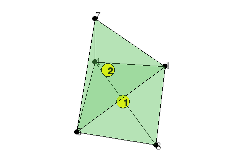
Example
We show two tetrahedron with the ascending ordering.
% A mesh with two tetrahedron with the ascending ordering
elem = [1 4 5 8; 1 4 5 7];
node = [1,0,0; 1,1,1; 1,-1,-1; 0,1,0; -2,-1,0; 1,1,-1; 0,1,1; 0,-1,-1];
NT = size(elem,1);
showmesh3(node,elem,[],'FaceAlpha',0.25);
findelem3(node,elem);
findnode3(node,elem(:));
display(elem);
% generate edge array
totalEdge = uint32([elem(:,[1 2]); elem(:,[1 3]); elem(:,[1 4]); ...
                    elem(:,[2 3]); elem(:,[2 4]); elem(:,[3 4])]);
sortedTotalEdge = sort(totalEdge,2);
[edge, ~, je] = unique(sortedTotalEdge,'rows');
display(edge);
% generate face array
totalFace = uint32([elem(:,[2 3 4]); elem(:,[1 4 3]); ...
                    elem(:,[1 2 4]); elem(:,[1 3 2])]);
sortedTotalFace = sort(totalFace,2);
[face, i2, jf] = unique(sortedTotalFace,'rows');
display(face);
% generate pointers of indices
elem2edge = uint32(reshape(je,NT,6))
elem2face = uint32(reshape(jf,NT,4))
% find orientation of elem
[v,elemSign] = simplexvolume(node,elem)
elem =

     1     4     5     8
     1     4     5     7


 edge =
	9x2 uint32 matrix

   1   4
   1   5
   1   7
   1   8
   4   5
   4   7
   4   8
   5   7
   5   8


face =
   7x3 uint32 matrix

   1   4   5
   1   4   7
   1   4   8
   1   5   7
   1   5   8
   4   5   7
   4   5   8
elem2edge =
2x6 uint32 matrix
   1   2   4   5   7   9
   1   2   3   5   6   8


elem2face =
  2x4 uint32 matrix

   7   5   3   1
   6   4   2   1


v =
    0.6667
    0.6667


elemSign =
    -1
     1
Since we are using the ascending ordering, the inconsistency with the induced orientation is
elem2faceSign = [1 -1 1 -1];face2edgeSign = [1 -1 1];
Comments